CS 432 Project 2: Geometric Warping *
In this project you will create a Khoros kroutine which
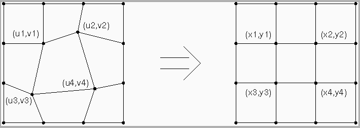
performs a control grid warping operation [See 8.3.5 of
Castleman]. The user specifies the position of four control
points. These define the central quadrilateral of an irregular 3 x 3
grid. The geometric warping operation maps the irregular 3 x 3 grid to
a regular 3 x 3 grid, i.e., it maps each of the nine quadrilateral
shaped regions in the source image to a corresponding rectangular
shaped region in the target image (see Figure 1 below).

To accomplish this, you will use a target-to-source mapping
strategy. This is facilitated by the fact that the regions of the
target grid are rectangular and aligned with the rows and columns of
the image as it is stored in memory. You will use bilinear
interpolation to compute the displacements (dx and
dy) which map a pixel in the target image to a point in the
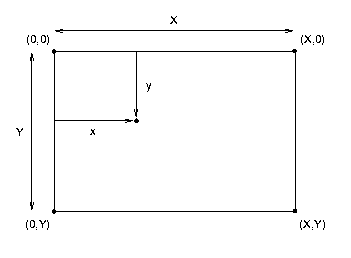
source image. Since you know 1) the values of dx and dy
at the four corners of the rectangle; and 2) the width and height
(X and Y) of the rectangle (see Figure 2 below), the
following equations allow you to compute dx and dy
at location (x,y) inside the rectangle:
- dx(x,y) = [dx(X,0) - dx(0,0)](x/X) + [dx(0,Y)-dx(0,0)](y/Y) + [dx(X,Y) +
dx(0,0)-dx(0,Y)-dx(X,0)](x/X)(y/Y) + dx(0,0)
- dy(x,y) = [dy(X,0) - dy(0,0)](x/X) + [dy(0,Y)-dy(0,0)](y/Y) + [dy(X,Y) +
dy(0,0)-dy(0,Y)-dy(X,0)](x/X)(y/Y) + dy(0,0)

Given the displacements, dx and dy, and the indices of
the pixel in the target image, i and j, the location in
the source image is simply (i-dx,j-dy). You will then need to
use bilinear interpolation a third time to compute the value of the
intensity of the pixel in the target image given the values of the
intensities of the four pixels which straddle location
(i-dx,j-dy) in the source image:
- I(x,y) = [I(1,0) - I(0,0)]x + [I(0,1)-I(0,0)]y + [I(1,1) +
I(0,0)-I(0,1)-I(1,0)]xy + I(0,0)
where I(0,0) is
I(floor(i-dx),floor(j-dy)), I(0,1) is
I(floor(i-dx),ceil(j-dy)), etc. Note also that
x and y are now the differences between
(i-dx,j-dy) and (floor(i-dx),floor(j-dy)) and
that X=Y=1.
Project Outline
- Using Craftsman, create a toolbox.
- Using Craftsman, create a kroutine and call it kgridwarp.
- Create the GUI using Guise. Make eight input parameters of
type FLOAT to represent the coordinates of the corners of the central
quadrilateral of the source grid.
- After saving the .pane file and exiting Guise, open the
Command submenu of Composer and generate
kgridwarp.c and associated files.
- Using cut and paste, edit kgridwarp.c so that it resembles
the template provided below.**
- Add your own code.
- Select Make Install in the Command submenu of
Composer to make and install the kroutine.
- Test it in Cantata.
Code Template
You can download a template of the kroutine by clicking here. This template includes all Khoros
system calls, helpful macros to access pixels, variables to hold the
dimensions of the value segment, and pointers to the input and output
data. Places where you can define additional variables, add your own
code and define additional procedures are indicated by comments.
Hints
- Interesting input images can be found using a web search engine. Good
keywords to try are: oblique, aerial and image.
- Use xv to convert an input image from the web to greyscale
and save it in .pgm format.
- You can assume that the input and output images are of type DOUBLE.
- Remember that the values of all input parameters are contained in a
structure called clui_info. For example, if you defined a FLOAT
variable called u1 in Guise then the value of that variable
will be contained in clui_info->u1_float.
- Modular design is good. Write a procedure warp_region and call
it nine times.
- Debug using a small (e.g., 32 x 32) image and get it working
before you try a larger image.
- For debugging purposes, the following C code will bring up an
information window and then print the value of x:
kfprintf(kstderr,"x = %f \n", x);
- Make sure that your program works when the source grid and
target grid are the same. If it doesn't work for this case it won't
work in more interesting cases.
- Make sure that you understand the expressions for bilinear
interpolation and are using them properly. Don't forget that the
expressions (as given) assume that the location of the upper left corner
is (0,0) and that the Y-axis is inverted. For regions other than
the upper left region of the target image, they will have to be modified.
- Read the previous hint again.
- Check boundary cases. If your code doesn't compute the correct
values for the four corners, it won't work for interior points.
- You might want to move the pixel access macros from kgridwarp.c
to kgridwarp.h. Then they won't be wiped out if you have
to generate the .c, .h, and .pane files again, e.g.,
because you made changes to the GUI.
- floor and ceil take arguments of type DOUBLE and return type DOUBLE.
- The source code for the example discussed in class can
be downloaded by clicking here.
- Start early!! Do the tutorial distributed in class and be comfortable
with the CASE tools before you attempt the project.
What It Should Look Like

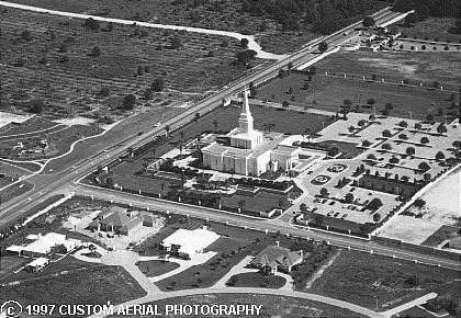
An oblique aerial image of a church.

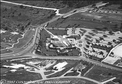
Same image after geometric warping operation.
What You Should Hand In ***
- A well documented listing of kgridwarp.c
- Hardcopy of an input image of your choice.
- Hardcopy of the same image after geometric warping.
- A screen dump of the GUI for your kroutine showing
its layout and the values of the input parameters used
to create the output image.
When You Should Hand It In
The above items should be handed in at the beginning of class on
Wed. Mar. 1, 2000.
* This webpage is located at http://cs.unm.edu/~williams/cs432/project2s00.html
** Alternatively, you can find kgridwarp.c under the toolboox
directory hierarchy and replace it with the template.
*** Curtis Sirl-Moore and James Corey didn't find the above project
challenging enough (and obviously have way too much free time on their
hands). Click here to see one of their
more advanced experiments with geometric warping.


